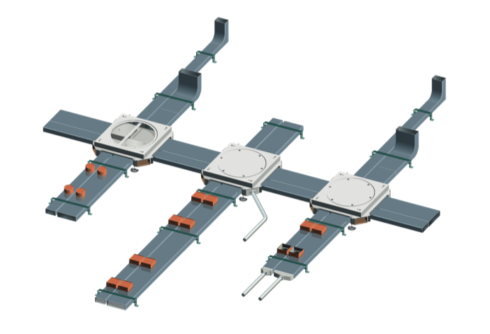
Walkerduct Flexible In-Floor Duct System
The Walkerduct system provides wire management for open space environments while maintaining aesthetics of the space with duct that is buried in the floor and activations that can be placed on top of the runs for easy access to power and data. Two types of presets are available, including rectangular Pro Series and round IPS Series presets. Choose from a wide variety of service fittings, including flush and pedestal styles.Duct runs are designed to be used with Walkerduct junction boxes or Trenchduct to create an in-floor wire management system. It’s an ideal configuration for casinos, commercial offices, education, government, museums, and retail applications.
Top Resources:
Explore the technical specifications and component overviews of the Walkerduct system.
Leverage pre-written specification documentation when building out a project's specification.
System Features
16-gauge galvannealed steel with continuous seam weld construction prevents moisture in the duct.
The system includes ducts of two sizes, No. 2 and No. 4 ducts. Mix and match duct sizes to accommodate runs that meet the needs of your application.
Flush-style activations available for both tiled and carpeted floors.
Ducts are available with or without presets. Ducts with preset are offered with spacing of either 12” or 24” between and include either presets in ½” increments from 1” to 3”.
Rectangular presets accommodate a large variety of service fittings, including flush options, while providing ample bend radius to ensure the integrity of fiber optic cable connections.
Round presets offer smaller egress areas. These work with pedestal style activations and are ideal for furniture feed applications.
Boxes can also be field-attached after concrete pour. Aftersets are available in a range of depths. Compatible 1200 Series, 525 Series, Multiplex, Pro Series, Source I Series service fittings.
Listed to UL Standard 884. Walkerduct can be fed by junction boxes or by Trenchduct for larger cable capacity installations.
Start at the end user's needs and work your way back through the system. Per desk, slot machine, retail cash register, piece of equipment, etc. how many circuits are required, what type of data is required, etc. The circuits and data needed per piece of equipment, along with that equipment's layout in a given space, will determine the number and size of the ducts in the distribution system. Besides the end user's needs, the second most important requirement is the slab depth.
Walkerduct can be configured to account for different slab depths, but the slab depth will drive many of the part numbers required for the system. Ducts in the distribution system often run at a 45 degree angle to the space's horizontal/vertical layouts to accommodate future moves, adds, and changes.
Junction boxes are positioned throughout the system to help pull wires through the system. Junction boxes also act as locations to bring conduit to for additional feeding of the distribution system. Walkerduct is also compatible with Trenchduct, which is often used as a feeder system back to the electrical panel.

Additional Resources
| Resource Description | Resource Type | Link to Download |
|---|---|---|
| BIM Models | Revit (.RFA) | Link |
| CAD Drawings | AutoCAD (.dxf) | Link |
| Cut Sheets | Acrobat (PDF) | Link |
| Guide Form Specs | Microsoft Word (.DOC) | Link |
| Installation Instructions | Acrobat (PDF) | Link |
| On-Grade Applications | Acrobat (PDF) | Link |
| Scrub Water Exclusion | Acrobat (PDF) | Link |


